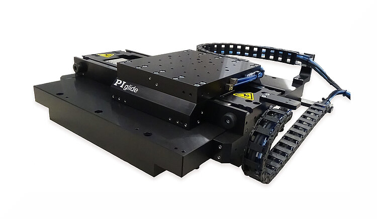
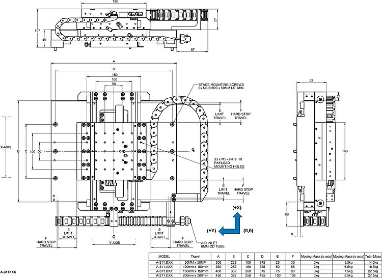
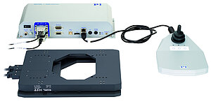
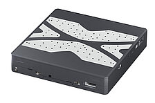
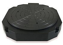
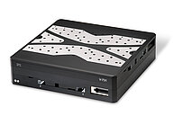
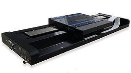
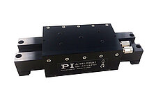
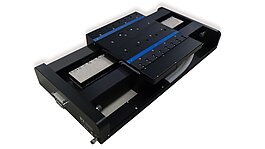
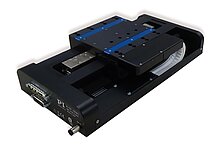
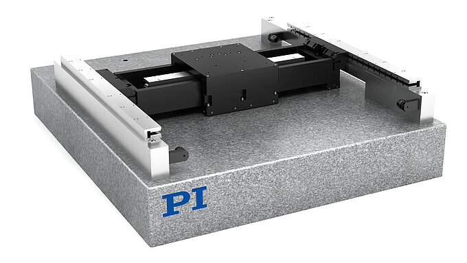
PIglide IS planar scanner with air bearing; ironless 3-phase linear motor; 50 mm × 50 mm travel range (X × Y); 147 N load capacity; 2000 mm/s × 2000 mm/s maximum velocity; incremental linear encoder, 20 µm sensor signal period, sin/cos, 1 V peak-peak
A-311 PIglide IS Planar Scanner with Air Bearing
High-Performance, Compact XY Nanopositioning System
- Ideal for scanning applications or high-precision positioning
- Cleanroom compatible
- Travel ranges to 300 mm × 400 mm
- Load capacity to 147 N
- Low profile
- Resolution to 1 nm
Product overview
The high-precision PIglide IS XY planar scanner with air bearing has a flat design and is an alternative to the stacked XY stages. The efficient, compact design saves space in machines with limited installation space.
PIMag® magnetic direct drive
3-phase magnetic direct drives do not use mechanical components in the drivetrain, they transmit the drive force to the motion platform directly and without friction. The drives reach high velocities and accelerations. Ironless motors are particularly suitable for positioning tasks with the highest demands on precision because there is no undesirable interaction with the permanent magnets. This allows smooth running even at the lowest velocities and at the same time, there is no vibration at high velocities. Nonlinearity in control behavior is avoided and any position can be controlled easily. The drive force can be set freely.
Operation with digital controllers from leading manufacturers offers advanced control algorithms for improving the dynamics and error compensation.
Accessories and options
- Encoder
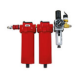
- PIglide filter and air preparation kit (version with vacuum generation required for models from 300 mm travel range)
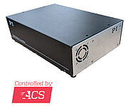
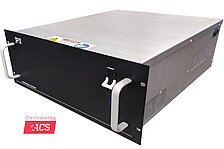
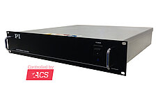
- Multi-axis motion controller and direct drives
- Machine bases
- Base plates made of granite and systems for reducing vibration
Application fields
PIglide positioning systems are ideally suited for high-precision applications, such as inspection systems, laser marking, microscopy or scanning.
Specifications
Specifications
| Motion | A-311.DA1 | A-311.DB1 | A-311.AA1 | A-311.AB1 | A-311.BA1 | A-311.BB1 | A-311.CA1 | A-311.CB1 | A-311.FB1 | A-311.GB1 | Tolerance |
|---|---|---|---|---|---|---|---|---|---|---|---|
| Active axes | X ǀ Y | X ǀ Y | X ǀ Y | X ǀ Y | X ǀ Y | X ǀ Y | X ǀ Y | X ǀ Y | X ǀ Y | X ǀ Y | |
| Travel range in X | 50 mm | 50 mm | 100 mm | 100 mm | 150 mm | 150 mm | 200 mm | 200 mm | 300 mm | 300 mm | |
| Travel range in Y | 50 mm | 50 mm | 100 mm | 100 mm | 150 mm | 150 mm | 200 mm | 200 mm | 300 mm | 400 mm | |
| Acceleration in X, unloaded | 27.5 m/s² | 27.5 m/s² | 27.5 m/s² | 27.5 m/s² | 27.5 m/s² | 27.5 m/s² | 27.5 m/s² | 27.5 m/s² | 10 m/s² | 10 m/s² | max. |
| Acceleration in Y, unloaded | 15 m/s² | 15 m/s² | 13 m/s² | 13 m/s² | 11 m/s² | 11 m/s² | 10 m/s² | 10 m/s² | 10 m/s² | 10 m/s² | max. |
| Maximum velocity in X, unloaded | 2000 mm/s | 2000 mm/s | 2000 mm/s | 2000 mm/s | 2000 mm/s | 2000 mm/s | 2000 mm/s | 2000 mm/s | 1000 mm/s | 1000 mm/s | |
| Maximum velocity in Y, unloaded | 2000 mm/s | 2000 mm/s | 2000 mm/s | 2000 mm/s | 2000 mm/s | 2000 mm/s | 2000 mm/s | 2000 mm/s | 1000 mm/s | 1000 mm/s | |
| Orthogonality | ± 12.5 µrad | ± 12.5 µrad | ± 12.5 µrad | ± 12.5 µrad | ± 12.5 µrad | ± 12.5 µrad | ± 12.5 µrad | ± 12.5 µrad | ± 10 µrad | ± 25 µrad | typ. |
| Straightness error E_XY (straightness) | ± 0.25 µm | ± 0.25 µm | ± 0.25 µm | ± 0.25 µm | ± 0.25 µm | ± 0.25 µm | ± 0.5 µm | ± 0.5 µm | ± 1 µm | ± 1 µm | max. |
| Straightness error E_YX (straightness) | ± 0.25 µm | ± 0.25 µm | ± 0.25 µm | ± 0.25 µm | ± 0.25 µm | ± 0.25 µm | ± 0.5 µm | ± 0.5 µm | ± 1 µm | ± 1 µm | max. |
| Straightness error E_ZX (flatness) | ± 0.25 µm | ± 0.25 µm | ± 0.25 µm | ± 0.25 µm | ± 0.5 µm | ± 0.5 µm | ± 0.75 µm | ± 0.75 µm | ± 1.5 µm | ± 1.5 µm | max. |
| Straightness error E_ZY (flatness) | ± 0.25 µm | ± 0.25 µm | ± 0.25 µm | ± 0.25 µm | ± 0.5 µm | ± 0.5 µm | ± 0.75 µm | ± 0.75 µm | ± 1.5 µm | ± 1.5 µm | max. |
| Angular error E_AY (pitch) | ± 10 µrad | ± 10 µrad | ± 12.5 µrad | ± 12.5 µrad | ± 17.5 µrad | ± 17.5 µrad | ± 20 µrad | ± 20 µrad | ± 20 µrad | ± 20 µrad | max. |
| Angular error E_BX (pitch) | ± 10 µrad | ± 10 µrad | ± 12.5 µrad | ± 12.5 µrad | ± 17.5 µrad | ± 17.5 µrad | ± 20 µrad | ± 20 µrad | ± 20 µrad | ± 20 µrad | max. |
| Angular error E_CX (yaw) | ± 5 µrad | ± 5 µrad | ± 5 µrad | ± 5 µrad | ± 7.5 µrad | ± 7.5 µrad | ± 10 µrad | ± 10 µrad | ± 10 µrad | ± 10 µrad | max. |
| Angular error E_CY (yaw) | ± 5 µrad | ± 5 µrad | ± 5 µrad | ± 5 µrad | ± 7.5 µrad | ± 7.5 µrad | ± 10 µrad | ± 10 µrad | ± 10 µrad | ± 10 µrad | max. |
| Positioning | A-311.DA1 | A-311.DB1 | A-311.AA1 | A-311.AB1 | A-311.BA1 | A-311.BB1 | A-311.CA1 | A-311.CB1 | A-311.FB1 | A-311.GB1 | Tolerance |
| Positioning accuracy in X, calibrated | ± 0.2 µm | ± 0.2 µm | ± 0.2 µm | ± 0.2 µm | ± 0.2 µm | ± 0.2 µm | ± 0.2 µm | ± 0.2 µm | ± 0.2 µm | ± 0.2 µm | typ. |
| Positioning accuracy in X, uncalibrated | ± 1 µm | ± 1 µm | ± 1.5 µm | ± 1.5 µm | ± 2 µm | ± 2 µm | ± 2.5 µm | ± 2.5 µm | — | — | typ. |
| Positioning accuracy in Y, calibrated | ± 0.2 µm | ± 0.2 µm | ± 0.2 µm | ± 0.2 µm | ± 0.2 µm | ± 0.2 µm | ± 0.2 µm | ± 0.2 µm | ± 0.2 µm | ± 0.2 µm | typ. |
| Positioning accuracy in Y, uncalibrated | ± 1 µm | ± 1 µm | ± 1.5 µm | ± 1.5 µm | ± 2 µm | ± 2 µm | ± 2.5 µm | ± 2.5 µm | — | — | typ. |
| Bidirectional repeatability in X | 0.1 µm | 0.1 µm | 0.1 µm | 0.1 µm | 0.1 µm | 0.1 µm | 0.1 µm | 0.1 µm | 0.1 µm | 0.1 µm | max. |
| Bidirectional repeatability in Y | 0.1 µm | 0.1 µm | 0.1 µm | 0.1 µm | 0.1 µm | 0.1 µm | 0.1 µm | 0.1 µm | 0.1 µm | 0.1 µm | max. |
| Reference switch | Encoder index | — | Encoder index | — | Encoder index | — | Encoder index | — | — | — | |
| Limit switches | Hall effect, N/O contact, 5 V to 24 V, open collector | — | Hall effect, N/O contact, 5 V to 24 V, open collector | — | Hall effect, N/O contact, 5 V to 24 V, open collector | — | Hall effect, N/O contact, 5 V to 24 V, open collector | — | — | — | |
| Integrated sensor | Incremental linear encoder | Absolute linear encoder | Incremental linear encoder | Absolute linear encoder | Incremental linear encoder | Absolute linear encoder | Incremental linear encoder | Absolute linear encoder | Absolute linear encoder | Absolute linear encoder | |
| Sensor signal | Sin/cos, 1 V peak-to-peak | BiSS-C | Sin/cos, 1 V peak-to-peak | BiSS-C | Sin/cos, 1 V peak-to-peak | BiSS-C | Sin/cos, 1 V peak-to-peak | BiSS-C | BiSS-C | BiSS-C | |
| Sensor signal period | 20 µm | — | 20 µm | — | 20 µm | — | 20 µm | — | — | — | |
| Sensor resolution | 1.2 nm | 1 nm | 1.2 nm | 1 nm | 1.2 nm | 1 nm | 1.2 nm | 1 nm | 1 nm | 1 nm | |
| Drive properties | A-311.DA1 | A-311.DB1 | A-311.AA1 | A-311.AB1 | A-311.BA1 | A-311.BB1 | A-311.CA1 | A-311.CB1 | A-311.FB1 | A-311.GB1 | Tolerance |
| Drive type | Ironless 3-phase linear motor | Ironless 3-phase linear motor | Ironless 3-phase linear motor | Ironless 3-phase linear motor | Ironless 3-phase linear motor | Ironless 3-phase linear motor | Ironless 3-phase linear motor | Ironless 3-phase linear motor | Ironless 3-phase linear motor | Ironless 3-phase linear motor | |
| Nominal voltage | 48 V | 48 V | 48 V | 48 V | 48 V | 48 V | 48 V | 48 V | 48 V | 48 V | |
| Peak voltage | 80 V | 80 V | 80 V | 80 V | 80 V | 80 V | 80 V | 80 V | 80 V | 80 V | |
| Nominal current, RMS | 3.2 A | 3.2 A | 3.2 A | 3.2 A | 3.2 A | 3.2 A | 3.2 A | 3.2 A | 2.9 A | 2.9 A | typ. |
| Peak current, RMS | 6.9 A | 6.9 A | 6.9 A | 6.9 A | 6.9 A | 6.9 A | 6.9 A | 6.9 A | 10 A | 10 A | typ. |
| Drive force in X | 39 N | 39 N | 39 N | 39 N | 39 N | 39 N | 39 N | 39 N | 58 N | 58 N | typ. |
| Drive force in Y | 39 N | 39 N | 39 N | 39 N | 39 N | 39 N | 39 N | 39 N | 58 N | 58 N | typ. |
| Peak force in X | 85 N | 85 N | 85 N | 85 N | 85 N | 85 N | 85 N | 85 N | 200 N | 200 N | |
| Peak force in Y | 85 N | 85 N | 85 N | 85 N | 85 N | 85 N | 85 N | 85 N | 200 N | 200 N | |
| Force constant | 12.3 N/A | 12.3 N/A | 12.3 N/A | 12.3 N/A | 12.3 N/A | 12.3 N/A | 12.3 N/A | 12.3 N/A | 19.9 N/A | 19.9 N/A | |
| Resistance phase-phase | 3.6 Ω | 3.6 Ω | 3.6 Ω | 3.6 Ω | 3.6 Ω | 3.6 Ω | 3.6 Ω | 3.6 Ω | 5.6 Ω | 5.6 Ω | typ. |
| Inductance phase-phase | 1.24 mH | 1.24 mH | 1.24 mH | 1.24 mH | 1.24 mH | 1.24 mH | 1.24 mH | 1.24 mH | 1.8 mH | 1.8 mH | |
| Back EMF phase-phase | 10.1 V·s/m | 10.1 V·s/m | 10.1 V·s/m | 10.1 V·s/m | 10.1 V·s/m | 10.1 V·s/m | 10.1 V·s/m | 10.1 V·s/m | 16 V·s/m | 16 V·s/m | max. |
| Pole pitch N-N | 30 mm | 30 mm | 30 mm | 30 mm | 30 mm | 30 mm | 30 mm | 30 mm | 30 mm | 30 mm | |
| Mechanical properties | A-311.DA1 | A-311.DB1 | A-311.AA1 | A-311.AB1 | A-311.BA1 | A-311.BB1 | A-311.CA1 | A-311.CB1 | A-311.FB1 | A-311.GB1 | Tolerance |
| Permissible push force in Z | 147 N | 147 N | 147 N | 147 N | 147 N | 147 N | 147 N | 147 N | 147 N | 147 N | max. |
| Moved mass in X, unloaded | 3000 g | 3000 g | 3000 g | 3000 g | 3000 g | 3000 g | 3000 g | 3000 g | 4000 g | 4000 g | |
| Moved mass in Y, unloaded | 5500 g | 5500 g | 6500 g | 6500 g | 7500 g | 7500 g | 8500 g | 8500 g | 12500 g | 15000 g | |
| Guide | Air bearing with air preload | Air bearing with air preload | Air bearing with air preload | Air bearing with air preload | Air bearing with air preload | Air bearing with air preload | Air bearing with air preload | Air bearing with air preload | Air bearing with vacuum preload | Air bearing with vacuum preload | |
| Overall mass | 14500 g | 14500 g | 18500 g | 18500 g | 22500 g | 22500 g | 27500 g | 27500 g | 48000 g | 55000 g | |
| Material | Hardcoat aluminum, stainless steel mounting hardware | Hardcoat aluminum, stainless steel mounting hardware | Hardcoat aluminum, stainless steel mounting hardware | Hardcoat aluminum, stainless steel mounting hardware | Hardcoat aluminum, stainless steel mounting hardware | Hardcoat aluminum, stainless steel mounting hardware | Hardcoat aluminum, stainless steel mounting hardware | Hardcoat aluminum, stainless steel mounting hardware | Hardcoat aluminum, stainless steel mounting hardware | Hardcoat aluminum, stainless steel mounting hardware | |
| Miscellaneous | A-311.DA1 | A-311.DB1 | A-311.AA1 | A-311.AB1 | A-311.BA1 | A-311.BB1 | A-311.CA1 | A-311.CB1 | A-311.FB1 | A-311.GB1 | Tolerance |
| Operating temperature range | +15 to +25 °C | +15 to +25 °C | +15 to +25 °C | +15 to +25 °C | +15 to +25 °C | +15 to +25 °C | +15 to +25 °C | +15 to +25 °C | +15 to +25 °C | +15 to +25 °C | |
| Connector | D-sub 9W4 (m) | D-sub 9W4 (m) | D-sub 9W4 (m) | D-sub 9W4 (m) | D-sub 9W4 (m) | D-sub 9W4 (m) | D-sub 9W4 (m) | D-sub 9W4 (m) | D-sub 3W3 (m) | D-sub 3W3 (m) | |
| Sensor connector | D-sub 15 (m) | D-sub 15 (m) | D-sub 15 (m) | D-sub 15 (m) | D-sub 15 (m) | D-sub 15 (m) | D-sub 15 (m) | D-sub 15 (m) | D-sub 15 (m) | D-sub 15 (m) | |
| Operating pressure | 415 to 485 (60 to 70 psi) kPa | 415 to 485 (60 to 70 psi) kPa | 415 to 485 (60 to 70 psi) kPa | 415 to 485 (60 to 70 psi) kPa | 415 to 485 (60 to 70 psi) kPa | 415 to 485 (60 to 70 psi) kPa | 415 to 485 (60 to 70 psi) kPa | 415 to 485 (60 to 70 psi) kPa | 415 to 485 (60 to 70 psi) kPa | 415 to 485 (60 to 70 psi) kPa | |
| Air consumption | 56 L/min | 56 L/min | 56 L/min | 56 L/min | 56 L/min | 56 L/min | 56 L/min | 56 L/min | 56 L/min | 56 L/min | max. |
| Air quality | Clean (filtered up to 1.0 µm or better) - ISO 8573–1 class 1 ǀ Oil free - ISO 8573–1 class 1 ǀ Dry (-15 °C dew point) - ISO 8573–1 class 3 | Clean (filtered up to 1.0 µm or better) - ISO 8573–1 class 1 ǀ Oil free - ISO 8573–1 class 1 ǀ Dry (-15 °C dew point) - ISO 8573–1 class 3 | Clean (filtered up to 1.0 µm or better) - ISO 8573–1 class 1 ǀ Oil free - ISO 8573–1 class 1 ǀ Dry (-15 °C dew point) - ISO 8573–1 class 3 | Clean (filtered up to 1.0 µm or better) - ISO 8573–1 class 1 ǀ Oil free - ISO 8573–1 class 1 ǀ Dry (-15 °C dew point) - ISO 8573–1 class 3 | Clean (filtered up to 1.0 µm or better) - ISO 8573–1 class 1 ǀ Oil free - ISO 8573–1 class 1 ǀ Dry (-15 °C dew point) - ISO 8573–1 class 3 | Clean (filtered up to 1.0 µm or better) - ISO 8573–1 class 1 ǀ Oil free - ISO 8573–1 class 1 ǀ Dry (-15 °C dew point) - ISO 8573–1 class 3 | Clean (filtered up to 1.0 µm or better) - ISO 8573–1 class 1 ǀ Oil free - ISO 8573–1 class 1 ǀ Dry (-15 °C dew point) - ISO 8573–1 class 3 | Clean (filtered up to 1.0 µm or better) - ISO 8573–1 class 1 ǀ Oil free - ISO 8573–1 class 1 ǀ Dry (-15 °C dew point) - ISO 8573–1 class 3 | Clean (filtered up to 1.0 µm or better) - ISO 8573–1 class 1 ǀ Oil free - ISO 8573–1 class 1 ǀ Dry (-15 °C dew point) - ISO 8573–1 class 3 | Clean (filtered up to 1.0 µm or better) - ISO 8573–1 class 1 ǀ Oil free - ISO 8573–1 class 1 ǀ Dry (-15 °C dew point) - ISO 8573–1 class 3 | |
| Recommended controllers/drivers | A-81x, A-82x | A-81x, A-82x | A-81x, A-82x | A-81x, A-82x | A-81x, A-82x | A-81x, A-82x | A-81x, A-82x | A-81x, A-82x | A-81x, A-82x | A-81x, A-82x |
Note on straightness and angular errors: Dependent on the flatness of the surface, on which the stage is mounted.
Note on velocity and acceleration: It can be limited by payload, controller, or drive performance.
Note on permissible push force: Assumes that the payload center of gravity is centered no more than 50 mm above the motion platform. The stage is designed for horizontal operation only.
Note on sensor resolution: Assumes a 4096x interpolation. Contact PI for the use of other factors.
Note on positioning accuracy: Improved accuracy can be obtained with controller-based error compensation. The stage must be ordered with a controller from PI to reach these values.
Accuracy values assume short duration and do not consider the long-term effects of thermal drift on the stage.
Note on moved mass in Y: Value includes upper axis (X)
Note on operating pressure: To protect the stage against damage, it is recommended to connect an air pressure sensor to the Motion-Stop input of the controller.
All specifications apply per axis, if not otherwise described.
At PI, technical data is specified at 22 ±3 °C. Unless otherwise stated, the values are for unloaded conditions. Some properties are interdependent. The designation "typ." indicates a statistical average for a property; it does not indicate a guaranteed value for every product supplied. During the final inspection of a product, only selected properties are analyzed, not all. Please note that some product characteristics may deteriorate with increasing operating time.
Downloads
Product Note
Product Change Notification A-xxx.*C1
Datasheet
Documentation
User Manual A311D0002
A-311.FXx/.GXx PIglide: XY Planar Scanner with Air Bearings
User Manual A311D0001
A-311 PIglide IS: Planar XY Air Bearing Stage
3D Models
3-D model A-311
White Paper
Air Bearings: When to Use and When to Avoid in Your Motion Application
All Positioning Stages are not Created Equal. Author: Matt Reck, PI
Ask for a free quote on quantities required, prices, and lead times or describe your desired modification.
PIglide IS planar scanner with air bearing; ironless 3-phase linear motor; 50 mm × 50 mm travel range (X × Y); 147 N load capacity; 2000 mm/s × 2000 mm/s maximum velocity; absolute linear encoder, 1 nm sensor resolution, BiSS-C
PIglide IS planar scanner with air bearing; ironless 3-phase linear motor; 100 mm × 100 mm travel range (X × Y); 147 N load capacity; 2000 mm/s × 2000 mm/s maximum velocity; incremental linear encoder, 20 µm sensor signal period, sin/cos, 1 V peak-peak
PIglide IS planar scanner with air bearing; ironless 3-phase linear motor; 100 mm × 100 mm travel range (X × Y); 147 N load capacity; 2000 mm/s × 2000 mm/s maximum velocity; absolute linear encoder, 1 nm sensor resolution, BiSS-C
PIglide IS planar scanner with air bearing; ironless 3-phase linear motor; 150 mm × 150 mm travel range (X × Y); 147 N load capacity; 2000 mm/s × 2000 mm/s maximum velocity; incremental linear encoder, 20 µm sensor signal period, sin/cos, 1 V peak-peak
PIglide IS planar scanner with air bearing; ironless 3-phase linear motor; 150 mm × 150 mm travel range (X × Y); 147 N load capacity; 2000 mm/s × 2000 mm/s maximum velocity; absolute linear encoder, 1 nm sensor resolution, BiSS-C
PIglide IS planar scanner with air bearing; ironless 3-phase linear motor; 200 mm × 200 mm travel range (X × Y); 147 N load capacity; 2000 mm/s × 2000 mm/s maximum velocity; incremental linear encoder, 20 µm sensor signal period, sin/cos, 1 V peak-peak
PIglide IS planar scanner with air bearing; ironless 3-phase linear motor; 200 mm × 200 mm travel range (X × Y); 147 N load capacity; 2000 mm/s × 2000 mm/s maximum velocity; absolute linear encoder, 1 nm sensor resolution, BiSS-C
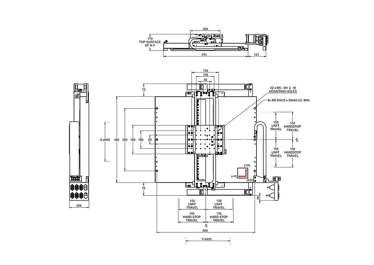
PIglide IS planar scanner with air bearing; ironless 3-phase linear motor; 300 mm × 300 mm travel range (X × Y); 147 N load capacity; 1000 mm/s × 1000 mm/s maximum velocity; absolute linear encoder, 1 nm sensor resolution, BiSS-C
PIglide IS planar scanner with air bearing; ironless 3-phase linear motor; 300 mm × 400 mm travel range (X × Y); 147 N load capacity; 1000 mm/s × 1000 mm/s maximum velocity; absolute linear encoder, 1 nm sensor resolution, BiSS-C
How to Get a Quote

Ask an engineer!
Quickly receive an answer to your question by email or phone from a local PI sales engineer.
